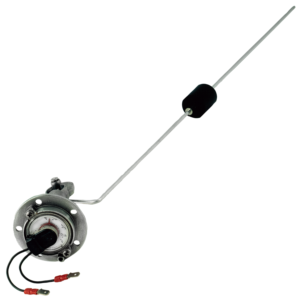
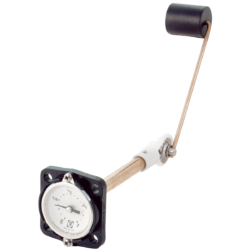
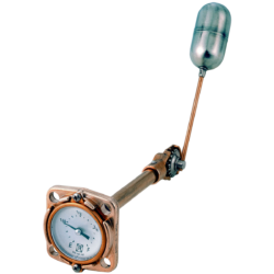
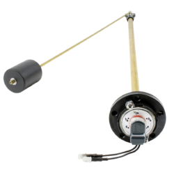
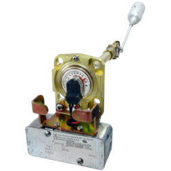
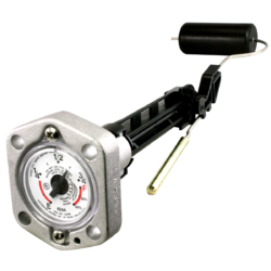
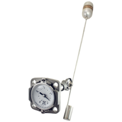
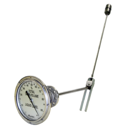
Description
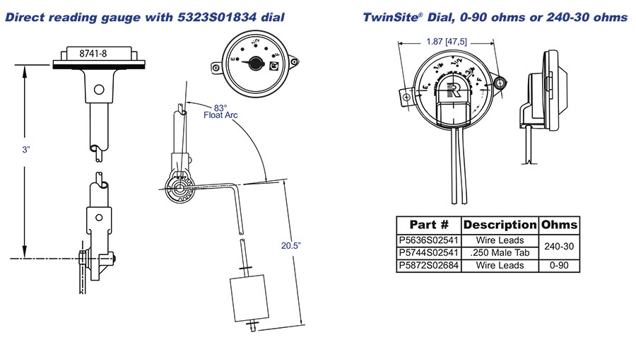
| Tank Depth in Inches | Distance from Float Bend to Float Rod Cut-off Point |
|---|---|
| 6 | 3″ |
| 7 | 3-3/4″ |
| 8 | 4-5/8″ |
| 9 | 5-5/8″ |
| 10 | 6-5/8″ |
| 11 | 7-5/8″ |
| 12 | 8-5/8″ |
| 13 | 9-3/4″ |
| 14 | 10-3/4″ |
| 15 | 11-3/4″ |
| 16 | 12-3/4″ |
| 17 | 13-3/4″ |
| 18 | 14-7/8″ |
| 19 | 15-7/8″ |
| 20 | 16-7/8″ |
| 21 | 17-7/8″ |
| Tank Depth in Inches | Distance from Float Bend to Float Rod Cut-off Point |
|---|---|
| 22 | 18-7/8″ |
| 23 | 20″ |
| 24 | 21″ |
| 25 | 22″ |
| 26 | 23″ |
| 27 | 24″ |
| 28 | 25-1/8″ |
| 29 | 26-1/8″ |
| 30 | 27-1/8″ |
| 31 | 28-1/8″ |
| 32 | 29-1/8″ |
| 33 | 30-1/4″ |
| 34 | 31-1/4″ |
| 35 | 32-1/4″ |
| 36 | 33-1/4″ |
General Specifications*
Mounting
Recommended for top-mounting only.
Accuracy
Accuracy depends upon proper gauge sizing. Junior dials ±7%, TwinSite® dials ±12%. Accuracy may be less depending upon tank shape. Accuracy may be less near full and empty. Accuracy may be less if tank is not level. This gauge is not to be used for filling. All accuracy estimates are expressed as a percent of full scale.
Temperature
Standard range is -40°F to 158°F, -40°C to 70°C.
Shock & Vibration
Suitable to mobile applications.
Power
0.5 watts maximum for TwinSite® versions.
Tank Pressure
0 to 10 PSIG [0 to 0,68 Bar].
Approvals
UL recognized for marine water service.
Note: Installation Instructions MS-533.
*Materials and specifications are subject to change without notice. Pressure ratings subject to change due to temperature and other environmental considerations.
Materials of Construction*
Head
Lightweight injection molded polyester SAE gasoline gauge flange (2-1/8″ [54] bolt circle for five #10 screws not furnished).
Centershaft, Support Tube & Float Rod
Brass.
Gears, Cross Stud & Bearing
Stainless steel.
Drive Magnet
Plated Alnico.
Gear Housing
Acetal.
Float
Nitrile rubber.
Gasket
Buna-N, 0015-00423.
Direct Reading Dial
Hermetically sealed polycarbonate.
TwinSite® Sender
Polyamide.
Dial Screws
Plastite 0040-00479.
When Ordering Specify:
1. Gauge model number.
2. Choice of dials.

