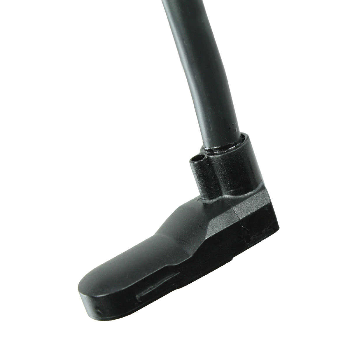
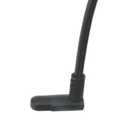
9701 Right Angle Modules
* Not recommended for new designs *
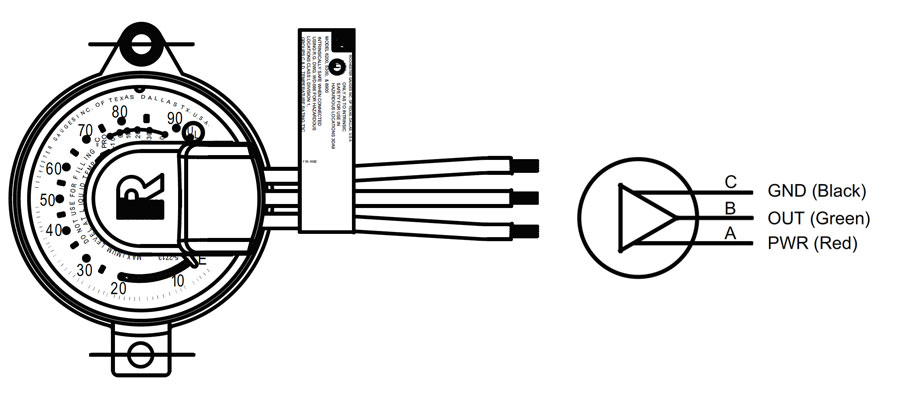
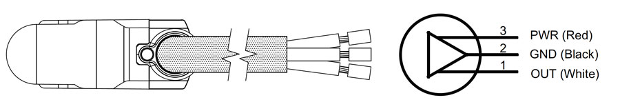
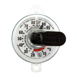
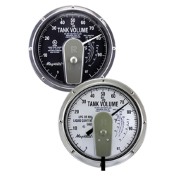
Notes for TwinSite® & Module :
- The Device is intended for supply voltage of 5 VDC, 4.5 to 5.5 VDC. Operating temperature -40° to 80°C.
- Over voltage 18V maximum.
- Reverse voltage -14.5V maximum.
- The typical current draw is 4.5mA.
- The output is ratiometric, percent of supply voltage, 1:1 Ratio.
- Settling time is1.5 Microseconds and does not include any circuitry outside TwinSite® or Module.
- Due to temperature compensation for magnet, voltage output will drift up to 40mV if power is applied for more than a few seconds.
- While maximum rated load is one mA, for best accuracy, the actual load should be 100 uA or less.
- Like many amplifiers, the output amplifier of the sender will become unstable when driving capacitive loads. These senders are usually stable with a maximum input resistance of 150 Ohms and with maximum load capacitance, including cable and load not over 0.3uF at room temperature. Careful design is required to minimize these factors. If they can not be eliminated, testing must be done to insure that the system operates correctly under all conditions.
- For Twinsite® control drawing, see WD-566.
- For wire attachment see DS-1014 and apply label 0115-01092 when installing wire.
- For Module control drawing see WD-570.
- For wire attachment see DS-1349 & DS-1387 and apply label 0115-01096 when installing wire.
- For ratios other than 1:1 see DS-1368 thru DS-1369.
- For vertical tanks see DS-1396.
- For 2.25 to 2.75 V operation see Hall Twinsite® with 2:1 voltage pump.
- For 3.00 to 3.6 V operation see Hall Twinsite® with 3:2 voltage pump.
WARNING: For LP-gas and other flammable product service applications, connect only to circuits and power sources Classified and labeled as
Intrinsically Safe for Class 1, Division 1, Group C and D hazardous locations. The connection of non-intrinsically safe power could cause fire or explosion
of flammable vapor which may be present.
Note: Materials and specifications are subject to change with out notice.
Documents
Data Sheet